Recomendar
Eliminar archivo
¿Eliminar documento <span id="remove-document-name"></span> del <span id="remove-cart-name"></span>?
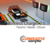
The WirelessCharger 3.0 is an industrial, wireless charging system, based on inductive coupling which provides automated contactless, fully intervention-free, and efficient battery charging for various kinds of vehicles, i.e. all kinds of Automated Guide Vehicles (AGVs), Autonomous Mobile Robots (AMRs / Cobots) or industrial trucks and forklifts.
Optimized, Efficient Charging
Using Lithium batteries, the charging process is optimized by a constant interaction between the onboard battery management system (BMS) and the Inductive Power Supply (IPS). The track supply only provides the instantaneously required power.
In contrast to conventional charging systems – conductive charging contacts and “plugged” inductive systems – the WirelessCharger 3.0 does not use any plugs or paddles and is fully intervention free.
Positioning the vehicle roughly over the Inductive Stationary Pad (ISP), the stationary coil is the only requirement. Charging can be fully automated.
Providing in-process charging automation capability, Wireless Chargers are ideal to apply opportunity charging. Short and frequent contactless charging intervals do reduce the thermal load on batteries, do extend their lifetime and make reduced battery capacities possible. Wirelss charging becomes a process integrated doing, there are no extended dead times for charging or travelling times to designated charging locations or even swapping batteries.

Safety Aspects
The geometry of the Conductix-Wampfler WirelessCharger 3.0 enables the Inductive Stationary Pad (ISP) and Inductive Mobile Pad (IMP) to contain the magnetic field mostly in the air gap between them.
No accidental switch on by different safety precautions, such as validations, pairing, defined charging orientation. When the vehicle is off the charging position, the track supply de-energizes the Inductive Stationary Pad, same when communication is not available.
By the nature of the power transfer means, there are no exposed contact surfaces. Pads are completely encapsulated and provide a high level IP-rating.
The Wireless Chargers are always following provided or pre-defined requirements, so the vehicle side determines the rate of power transfer. Typically with Lithium batteries they exclusively follow the charging requirements provided to the Mobile Power Unit (MPU).
System status provided to stationary and mobile control units through CAN and/or Ethernet interfaces. Ease of state recognition by the display on the Inductive Power Supply (IPS) and the halo light effect.
By design, the output is current limited. Onboard components are galvanically separated from the stationary components.
Communication between the mobile and the stationary side of the wireless charger by the means of inductive communication is unaffected by radio based communication, i.e. WiFi, used close by.
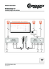
Operating Principle
Each wireless charger system consists of two parts, primary/stationary and secondary/mobile, which are magnetically coupled, similar to a conventional transformer. The primary or stationary side consists of an Inductive Power Supply (IPS) and an Inductive Stationary Pad (ISP). The secondary, or mobile vehicle side, consists of an Inductive Mobile Pad (IMP) and a Mobile Power Unity (MPU), installed onboard a vehicle.
Unlike a conventional transformer, where primary coil and secondary coil are mechanically coupled, the WirelessCharger 3.0 is a loosely coupled system operational with an air-gap.

Opportunity Charging / In-process Charging
Opportunity Charging or in-process charging means the use of available time slots during operations. Typically, these are short but frequent stops. Which means you never recharge the battery completely; you just refill it to a certain extend.
The WirelessCharger 3.0 is a system which enables vehicles such as Automated Guided Vehicles (AGVs) to operate fully on this principle on an ideal basis.
A minimal onboard energy storage, enough to reach the next contactless charging opportunity, becomes practically sufficient to operate AGVs.
This offers various practical scenarios:
10102 F Street
Omaha, NE 68127
United States
Teléfono: +1 (402) 339-9300
Fax: +1 (402) 339-9627
Toll Free: (800) 521-4888
www.conductix.us
info.us@conductix.com
vCard
Código de respuesta rápida
Dónde ubicarnos


